(AKA Photon stove)
Last updated 12-4-2001
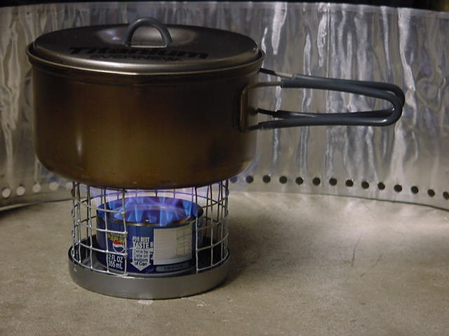
Performance:
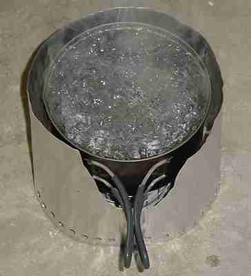
This stove out performs the Esbit in boil time and is equal in weight
of fuel required to boil 16 oz of water. Virtually no soot and no odor
other than alcohol fumes while you are filling the stove. If you include
the preheat time this stove is about as fast as a MSR Wisperlight at boiling
16 oz of water. An optional simmer ring is now included.
Click
here for the printable users guide and detailed weight and performance
information.
15 Second MPEG Videos:
Video
of lighting the stove (I had 15 seconds you have all the
time you need)
Video
of using Simmer Ring
Video of Simmering
CONSTRUCTION:
Follow these instructions exactly. If you make changes or adaptations even in the smallest way you will probably alter the stoves performance. Best results will be obtained by using the exact materials specified. The size of needle you use is critical. There are three designs for the filler hole that you can choose from. Click here for help in choosing which filler hole design is best for you. The heavy-duty filler hole design as shown in the pictures shows the option for attaching the filler hole screw to the stove with a chain but you can also use this design without the chain attachment.
Materials:
- 3 Soda cans - 12 oz size
- J-B Weld Epoxy available at Trak Auto and many other stores - says on back of package in upper left corner J-B Weld Maximum temperature is 600 degrees F
- Paper towel
- Flat type Toothpick - not a round one.
- Large 10 oz Tuna can, Chicken can or other can that is 4" in diameter
- 1/2" hardware cloth wire mesh
- MSR Wind Screen or make one like it from disposable EZ Foil type aluminum oven liners. Another option is to make one from heavy-duty aluminum foil doubled, tripled or more to increase durability.
- #8 X 1/2" Sheet metal screw
- #8 Aluminum screw - I use an aluminum thumbscrew like is used to attach screens to storm doors. Found at Hardware stores in the miscellaneous fastener area, storm or screen door parts area or window screen repair parts area. These are used for clamping a window screen to a storm door and they usually have the little aluminum clamps as well.
- 8/32 Steel Rivet Nut. http://jcwhitney.com/ Search for part number 81ZX0657R Picture at http://www.marsoncorp.com/klikrivetnuts.htm. Another possible source is auto body shops or parts stores.
- #8 Aluminum screw - I use an aluminum thumbscrew like is used to attach screens to storm doors. Found at Hardware stores in the miscellaneous fastener area, storm or screen door parts area or window screen repair parts area. These are used for clamping a window screen to a storm door and they usually have the little aluminum clamps as well.
- #8 Tap - used to clean the threads after installing the Rivet Nut
- Two #10 chain attachments for beaded chain
- 1" of light beaded chain like used for light fixtures
- #8 Aluminum nut -Found at hardware stores
The size of the needle is very important because using a larger needle reduces efficiency. The port size made by the Coats needle is between .024 and .025. The most certain way to get the correct port size is to drill the holes. You can drill the holes with a pin vise or Dremel tool and a .024 drill bit. You can find these numbered drill bits at hobby stores and some home centers. I don't know what needles from other manufacturers might be comparable so you will have to experiment on your own.1.5 tall can or other object - a 6 oz tuna can works Utility knife blade or other device to use for scribing a line Metal snips Paper punch Rough sandpaper or emery paper Hammer Smallest hand sewing needle - "Coats" brand "Betweens/Quilting" sz .9 qty 20 all the same size. Obtained from Wal-Mart or other source.
Tool needed specifically for the Light Duty filler hole option:
- Screw driver or nut driver sized for the #8 X 1/2" Sheet metal screw
- 3/16 Drill Bit
- Electric drill or drill press
BURNER CONSTRUCTION:Threaded Insert Riveter $12.99 ITEM 1210-1VGA at http://www.harborfreight.com (Don't use the rivets that come with it) 7/32 drill bit #8 -32 Tap and tap handle - used to clean the threads after installing the Rivet Nut Electric drill or drill press Hacksaw and fine tooth blade - for shortening the Rivet Nut
Light Duty Filler hole:
Standard Filler hole:
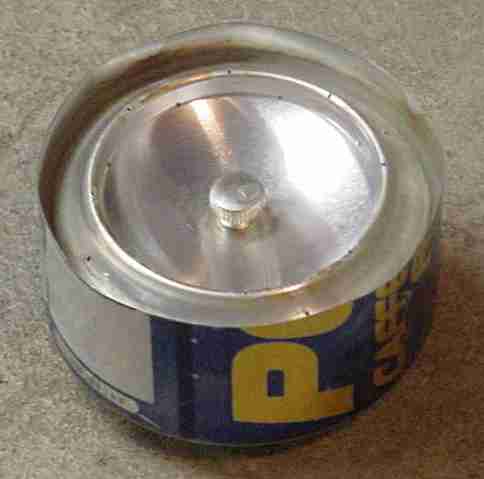
Heavy-Duty filler hole option:

Burner ports.
If you will be using a needle to make the burner ports that is done
after the burner is assembled so skip to "Continue construction of the
top of the burner" below. To avoid metal shavings in the burner drilled
ports need to be constructed now.
Drill the burner ports as follows.
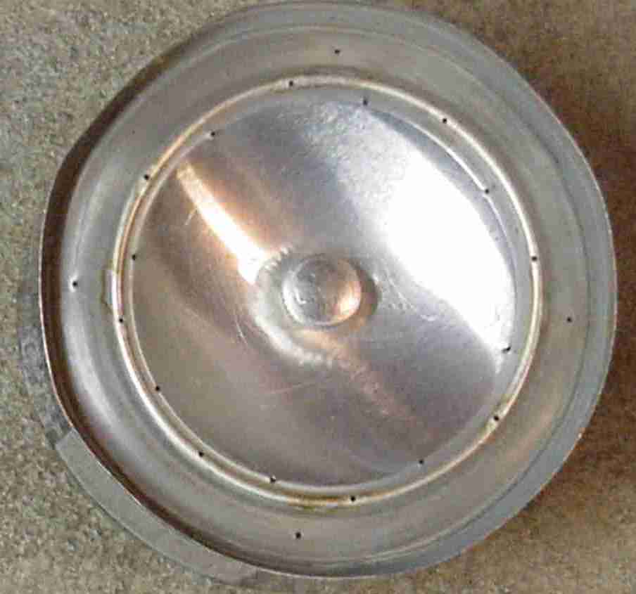
The colored lines represent the position and angle of the drill as
you make the burner ports.
Drill 8 holes evenly spaced around the inner base of the raised rim facing up at a 60-degree angle toward the center (Red in the picture). Drill 8 more holes facing as straight up as possible evenly spaced into the raised rim of the top of the inner can and spaced between the 8 holes you already punched (Blue in the picture). Most recently I have angled these holes toward the center also but I am not sure it makes any difference. Drill 4 more holes facing as straight up as possible evenly spaced around and halfway between the raised rim and the outer wall of the can (Violet in the picture). Despite the appearance in the left picture these should be slightly off set from the holes you drilled on the rim. The right picture shows the correct placement for all of the holes. The offset is to provide a clear path for air to get to the inner ring of holes.
Continue construction of the top of the burner as follows.
Take the other can that you set aside previously to be the bottom of the burner and roughen the inside wall with emery paper. This step is to increase the holding power of the epoxy as stated in its directions.

Let dry 15 hours.
Light Duty filler hole option:
Punched Burner Ports:
If you have already drilled the burner ports skip to "Complete Construction
of the Heavy-Duty filler hole" below.
The colored lines represent the position and angle of the needle as
you make the burner ports.
Using the small sewing needle and hammer make 8 holes evenly spaced around the inner base of the raised rim facing up at a 60-degree angle toward the center (Red in the picture). Hammer 8 more holes facing as straight up as possible evenly spaced into the raised rim of the top of the inner can and spaced between the 8 holes you already punched (Blue in the picture). Most recently I have angled these holes toward the center also but I am not sure it makes any difference. Hammer 4 more holes facing as straight up as possible evenly spaced around and halfway between the raised rim and the rim of the outer can (Violet in the picture). Despite the appearance in the left picture these should be slightly off set from the holes you drilled on the rim. The right picture shows the correct placement for all of the holes. The offset is to provide a clear path for air to get to the inner ring of holes.
Complete Constriction of the Heavy-Duty filler hole option: If not using the heavy duty filler hole option skip to Stove Base. Cut 1" of light chain and attach it to the chain fitting on the stove. Place a #6 chain fitting on the #6 thumb screw. Screw a #6 aluminum nut on the thumb screw and run it up so it holds the chain fitting up at the end of the threads but leaves it loose to rotate freely. Squeeze the aluminum Nut with pliers crimping the nut on the screw to make this permanent. Attach the chain to the chain fitting and squeeze the fittings closed to prevent the chain from coming out.
Construction of the burner is complete.
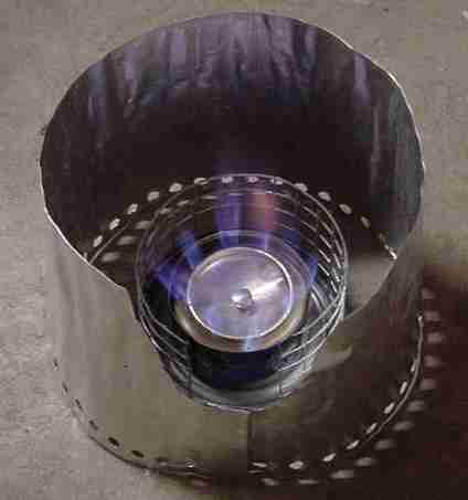
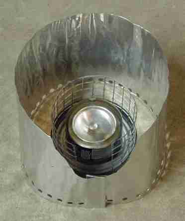
STOVE BASE:
POT SUPPORT:
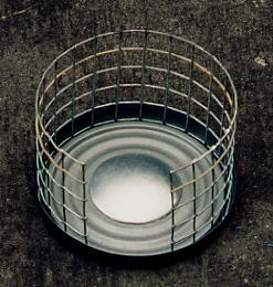
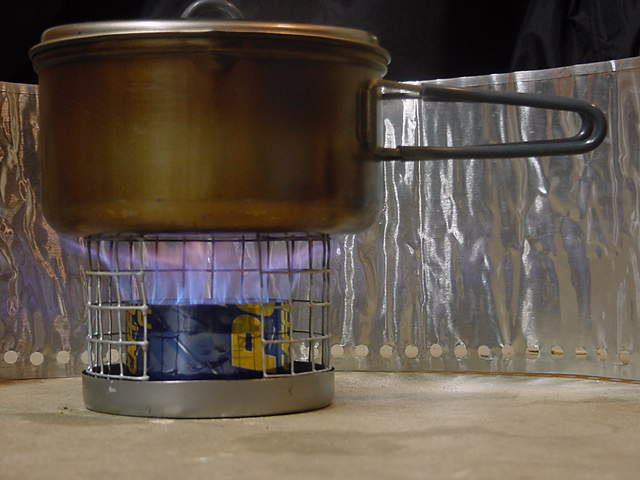
WIND SCREEN:
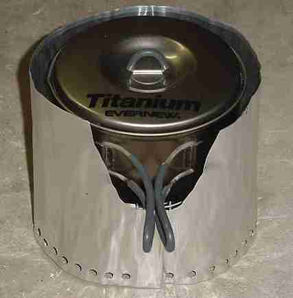
Place the pot you will cook in on the pot support then wrap the MSR
wind screen around them to leave about a 1/4 to 1/2" gap all the way around
between pot and wind screen. Fold the ends of the windscreen so they can
be hooked together to make a secure closure and cut off the excess material.
If you need to cut out a place for the pot handle to pass through do that
also.
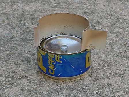
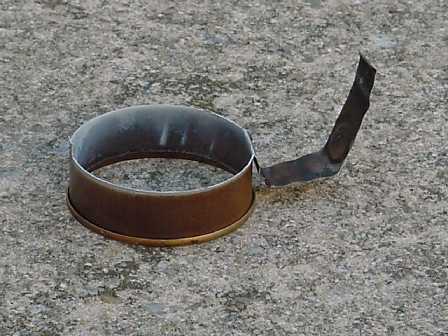
SIMMER RING
MATERIALS:
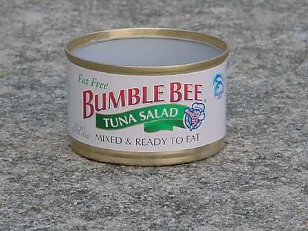
- One 3 oz Spam Spread can or Bumble Bee brand 2.9 oz Tuna salad can. The Tuna salad can comes packaged with crackers in a paper topped plastic package. A 5 oz Vienna Sausage can could be substituted if you can't find either of the other cans.
TOOLS:
The best tool for construction is a Dremel cutting wheel. It can be
used in a drill press, Dremel tool or a drill mounted in a drill press
stand. Set the desired height then rotate the work against the cut off
wheel to make the cuts. A very fine toothed hack saw blade could probably
be substituted but it will be a lot harder to avoid bending the can and
get a even height cut.
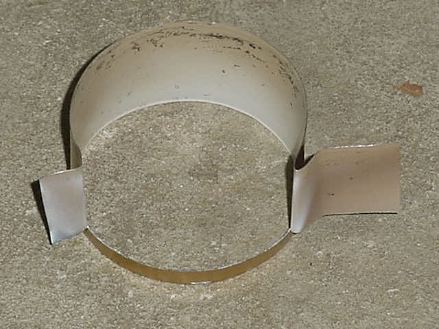
CONSTRUCTION:
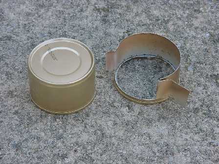
Before and after cutting
Setup the drill press or other tool so the bottom of the cutting wheel is about 1 and 9/16 above the surface. Better slightly too high than too low. Place the can rimmed side down and cut the bottom off of the can so both ends are open and the can ends up about 1 and 9/16 inch high. Lower the cutting wheel to 1/4 inch above the surface. Cut a 2 inch long slot 1/4 inch up from the rimmed end of the can. The two inches is measured as a straight line from one end of the slot to the other ignoring the curve of the can. Just slip the edge of your tape measure in the slot to measure the distance. 1 and 1/4 inches from one side of the slot cut straight down from the cut off end of the can to the slot creating two flaps. Fold back the 1 and 1/4 inch flap to become the handle. Cut off all but the last 1/4 inch of the other flap. The opening should now measure 1 and 3/4 inches. The 1/4 inch flap is to give you a choice of longest simmer or slightly shorter more reliable simmer. Fold out the last 1/4 inch to obtain the shorter more reliable simmer. A longer simmer can be obtained if you don't fold out this last 1/4 inch but the stove is more likely to go out before all of the fuel is used up especially in wind. You can always extend the slot if you find you need a hotter simmer. Adjust the width of the opening as desired for conditions.
Optional configurations:
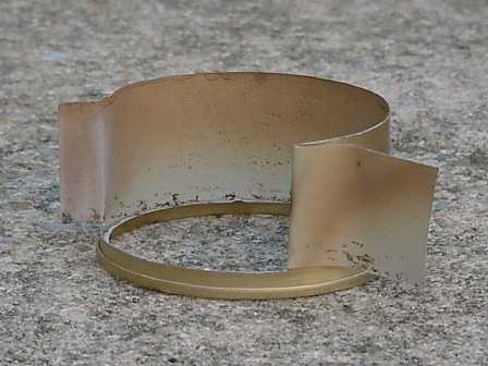
Rim cut off before construction
A lighter but less durable ring can be made by cutting off the rim of the can prior to construction. This reduces the weight to 0.1 oz
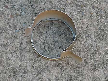
Non adjustable simmer ring.
A non adjustable simmer ring is easier to construct and will be very durable but more subject to variable behavior in wind. Construct it by cutting the bottom off of the can so both ends are open and the remaining can is about 13/16 of an inch high. You can fashion a handle by not cutting all the way around the can and forming a handle out of the attached bottom material by trimming excess material with metal snips.
STOVE ASSEMBLY:
Completing your stove system:
A one ounce plastic bottle with a flip top lid from REI is a handy
measuring container for filling the stove and providing an estimate of
how much fuel you are putting in. Make sure you squeeze the bottle before
you buy it to make sure you are not getting one with a flip top lid that
leaks. If you can't find one with a non-leaky flip top lid don't buy it.
A lighter alternative is using the bottom from a plastic salt and pepper
shaker set from REI which holds 0.6 oz in weight of fuel and weighs 0.1
ounce (REI item number is 601676). This prevents significant over filling
of the stove when all you want to boil is 16 oz of cold water. Filling
this container twice will boil 32 ounces of cold water. I found it useful
to scribe lines on these containers at 0.1 ounce (weight) intervals.
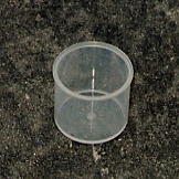
0.6 oz fuel measuring container created from REI item number 601676 salt and pepper shaker.
A Red Nalgene Fuel bottle that incorporates a pouring spout is handy for filling your measuring container but you may find a lighter container that works just as well for you. I find that a 16 oz drinking water bottle with a standard screw cap works well for me.
Do not use any fuel other than Alcohol. Denatured Alcohol is the recommended fuel. Denatured Alcohol is available almost anywhere paint is sold. This includes Hardware stores, Sears, WalMart, and building supply outfits like Home Depot. If you are doing a long hike and you want to resupply with fuel along the way there are two other options if you can't find Denatured Alcohol. I have tested with Everclear brand grain alcohol which is 95% Alcohol (190 proof) and the HEET brand of gas-line antifreeze that comes in a yellow container. Both work fine. Everclear is available in many Liquor stores and possibly bars. HEET and other brands of gas-line antifreeze can be found at some gas stations and many types of stores BUT read the label to be certain it contains Methyl Alcohol as its main ingredient. Gas-line antifreeze type products are frequently NOT Methyl alcohol and some are Isopropyl alcohol. Avoid Isopropyl alcohol. Read the label and don't buy it if in doubt. I strongly recommend against use of any form of Isopropyl alcohol including Rubbing alcohol. Rubbing alcohol that is 91 % will work if you are desperate but is really sooty so I very strongly recommend you avoid it. Rubbing alcohol that is 70 % or less is just not worth the mess or operational troubles if you can get it to work at all.
USERS GUIDE
Click
here for the printable users guide and detailed weight and performance
information..
TUNING
If your stove is not getting 16 oz of 50 degree water to boil in about 4:45 seconds you can tune the stove slightly to make it boil faster. The outer 4 ports can be angled toward the raised outside walls. This heats the walls more causing the fuel to be vaporized at a faster rate. Use the needle or drill bit to angle the port out ward toward the side wall. Do this carefully so you do not enlarge the ports.
Credits:
Most of the ideas incorporated in the design of this stove are not
original. I used many of the ideas in Thomas
Tveit Rosenlund's stove and incorporated them into the soda
can stove design. These stoves and more were all linked on Ron
"Fallingwater" Moak's Kiss Stove page. The idea of using a hand-sewing
needle to make the burner ports I got from Kevin Lane. My brother
David Johnston provided information on many performance issues dealing
with fuel mixture, port size, number of ports, and causes of soot.. For
suggesting that J-B Weld might meet my needs as a high temperature epoxy
Chuck Mohr and Dwayne Kib. Sealing the stove with epoxy to obtain
more control, the paper punch holes in the burner, number of ports and
port locations along with refinements into a complete easy to light system
were my ideas.
Disclaimer:
I do not know of anything unusually dangerous about this design and
I have done some out of the norm extreme testing to see if there are any
unusual or unexpected dangers. I did not find any and expect this stove
to be as safe as other home made alcohol stoves if you follow the directions
for construction and operation. That said, if you construct this stove
you do so entirely at your own risk. The stove YOU construct is unproved
and experimental and I strongly recommend you test your stove in a safe
test environment taking all precautions to protect life and property should
something-go wrong. You should wear safety clothing and glasses. This stove
can generate some internal pressure. I did a test on mine in which I filled
the burner with fuel and used an extremely large amount of preheat fuel
to simulate the most extreme overheat conditions I could. The burner shot
very long burner flames and alcohol vapor was exiting the stove at a faster
velocity than it could burn causing the flame to lift off the ports. Nothing
failed and no damage but clearly there was more internal pressure than
appropriate. Once the preheat fuel was exhausted the stove calmed down
to normal.
Copyright © 2000-2001 Donald H. Johnston
E-mail d.h.j@home.com